Ultrasonic beam alarm clock
September 2024 - May 2025
A modulated ultrasound array in an alarm clock that can only be heard from directly in front of it.
tldr
- Role
- Solo · funded by a Duke Co-Lab grant · Sep 2024–May 2025
- Built
- Designed a directional-speaker alarm clock: a custom PCB drives 18 ultrasonic transducers at 32 V, and STM32 firmware encodes a 600 Hz alarm into the 40 kHz beam
- Result
- Alarm audible only from directly in front of the clock; documented in a Duke Co-Lab write-up
- Tools
- PCB design, STM32, H-bridge driver, Python, power regulation
Read the Co-Lab project write-up (colab.duke.edu)opens in a new tab
My roommate and I had very different schedules freshman year. On days either of us planned to sleep late, it seemed that the other would always be up early, with a loud alarm waking the entire room.
I'd been looking for a reason to design a custom PCB, and I figured this would be as good an opportunity as any. I secured grant funding from Duke's Co-Lab and I was good to go. My writeup for them can be found here.
This project centers around modulated ultrasound: high frequency sound waves outside of the audible range that carry an audible signal which demodulates into audible sound locally in the air where the beam travels. This effect can be attributed to air's non-linear acoustics.
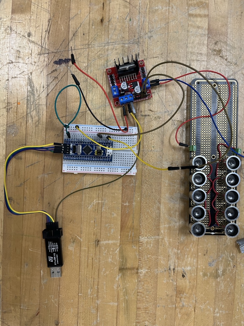
My first prototype was a protoboard with a dozen ultrasonic transducers powered by 24 volts through an H-bridge, with an STM32 sending my audio signal. I wrote a Python script to translate a 600 Hz (audible) sine wave into a 40 kHz square wave by modulating the duty cycle of the square wave. The output of my program was an array of 8-bit values that I hardcoded into the STM32 to play on repeat.
The resulting beam was audible from directly in front of the array, though it wasn't as loud as I hoped. The sound was limited by the 24V max output of the power supply, and the size of the array.
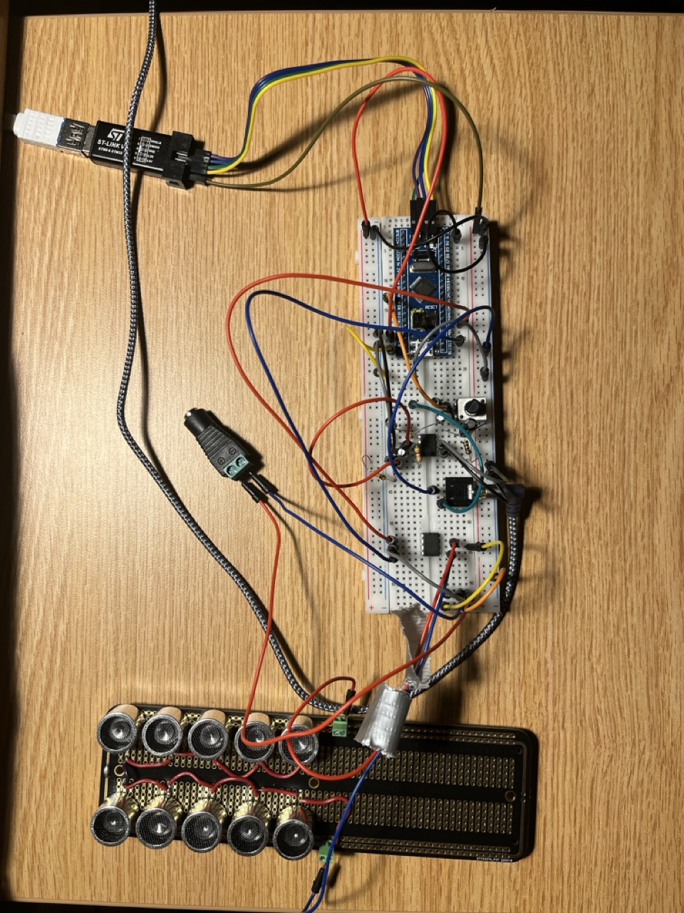
In the meantime, I assembled another prototype with an audio jack, op amp, and simple filter to encode audio from my laptop into the beam. This was more complex than what I needed on the alarm clock, but it was a cool toe-dip into audio engineering (video below).
With these promising results, I designed a custom board for a much larger array of TCT40-16 transducers and ordered components from AliExpress.
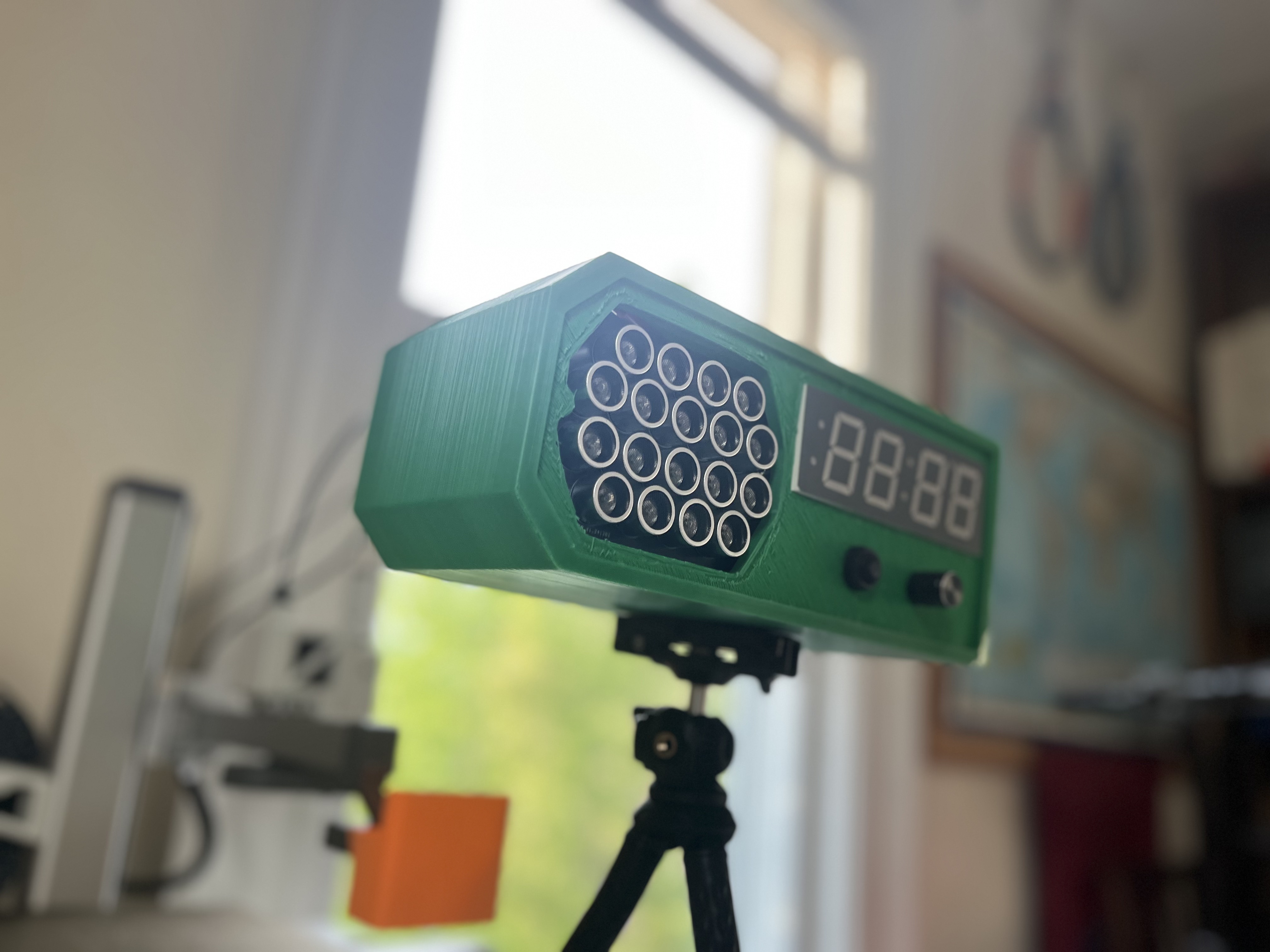
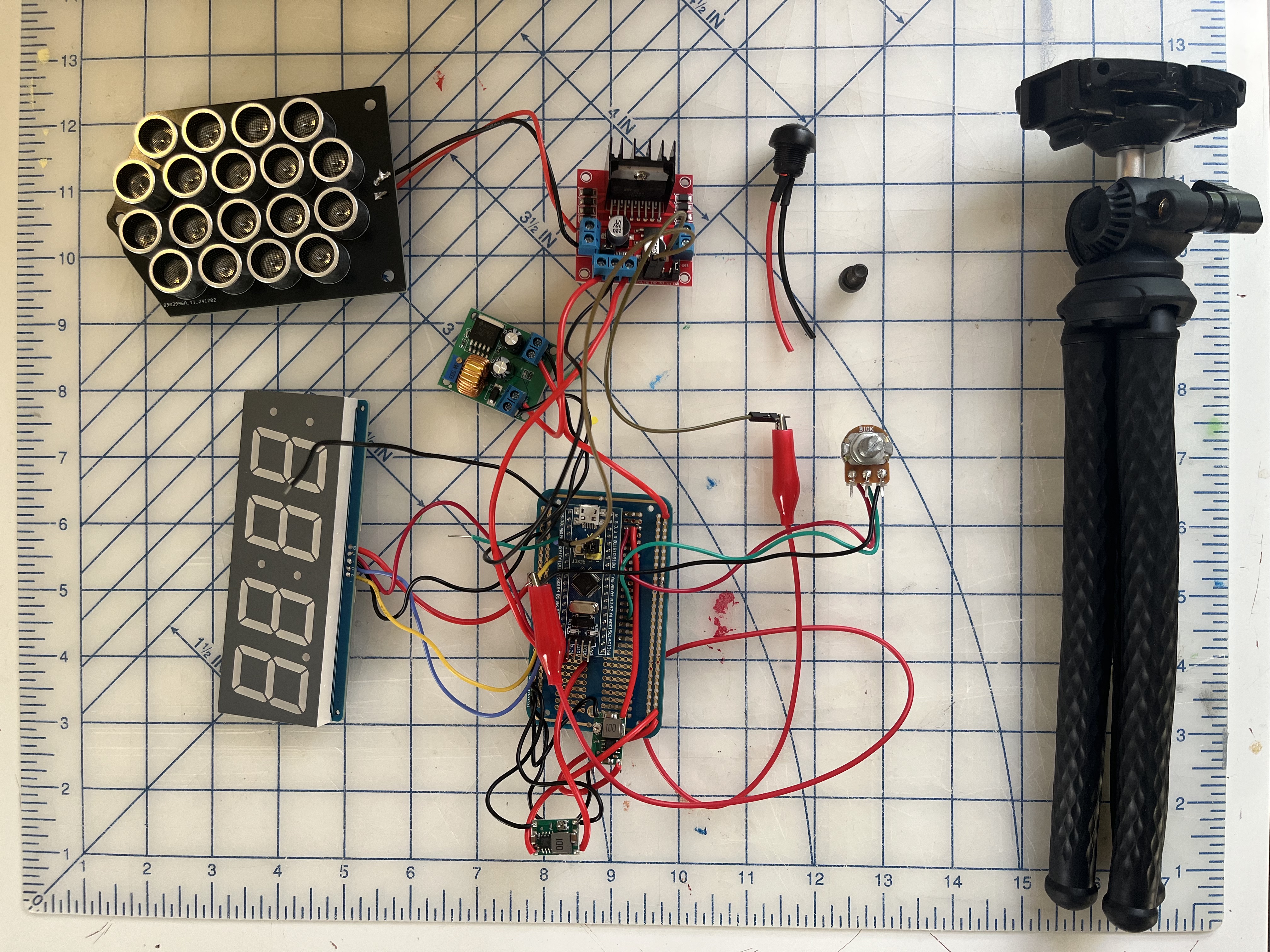
The final clock is pictured in the top right image. Its speaker array of 18 transducers receives 32V (still through an H-bridge). A 600 Hz sine wave is encoded in the narrow 40 kHz beam, which demodulates in the air it travels through (and more when it collides with a surface like a pillow). The clock's logic and RTC run on an STM32, adjusting the alarm time according to a potentiometer and button on the front (the alarm is disabled by turning the knob to the side). A 120V AC to 24V DC power supply powers the clock, with separate regulators for the logic (3.3V), speaker (32V), and display (5V) fitting inside. To aim the clock, I added a threaded insert on the bottom which mounts to a tripod.
I'd designed the clock to have a wooden accent and less-green enclosure, but the semester was quickly ending and I wanted to have it done before going home. In the end, the clock worked well enough for me to be proud of it, though the lack of volume control made it less desirable to use (and I started another sleep project I was more excited to adopt into my life). To read about that other project, which I have more than a thousand hours of usage on, read about it here: Circadian.