Jet engine for distributed manufacturing
September 2025 - January 2026
A majority-printed kerosene jet engine designed to be producible with only a lathe, 3-axis CNC, and SLM printer.
tldr
- Role
- Most of the final CAD · 2-person team with Marco Schonert · Sep 2025–Jan 2026
- Built
- Designed a turbojet around one metal-printed (SLM 316L) body integrating diffuser, guide vanes, combustor and oil lines; post-machined, balanced and assembled it
- Result
- Designed for 110,000 RPM on kerosene at a $2,000 cost target; first propane test reached ~30,000 RPM; 18-page write-up
- Tools
- CAD, SLM metal printing, lathe, 3-axis mill, rotor balancing
Read the Project Tyr technical write-up (PDF, 18 pages)11.6 MB, opens in a new tab
I joined my friend Marco in building a jet engine. The goal was to produce a small turbine engine using JLCPCB's laser-printed metal (SLM) services and standard machining available at Duke.
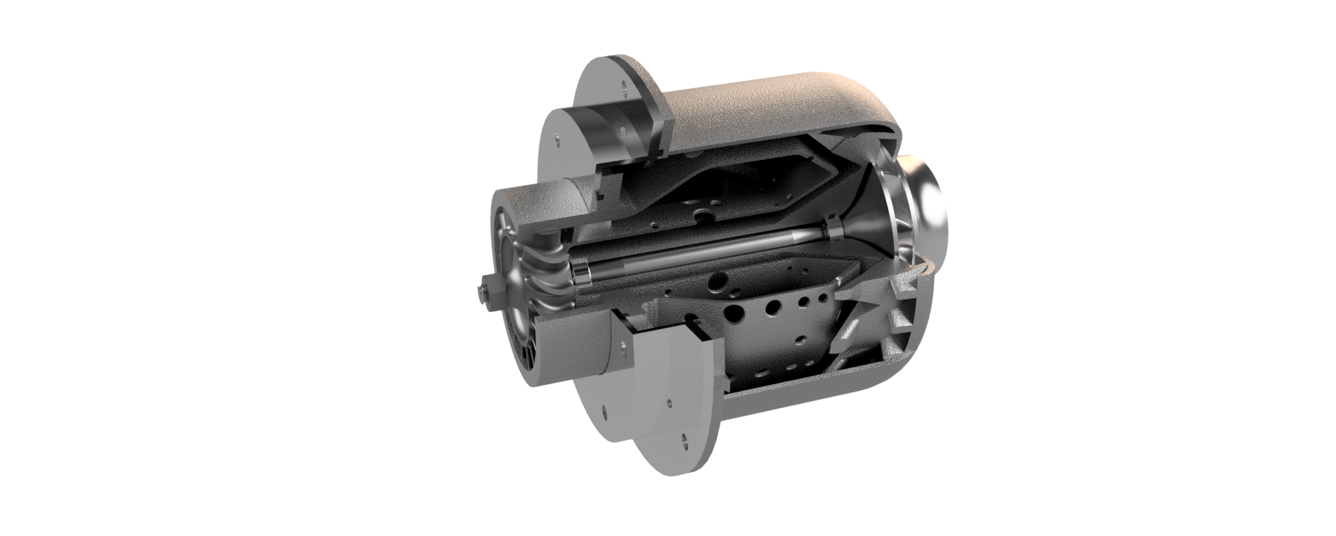
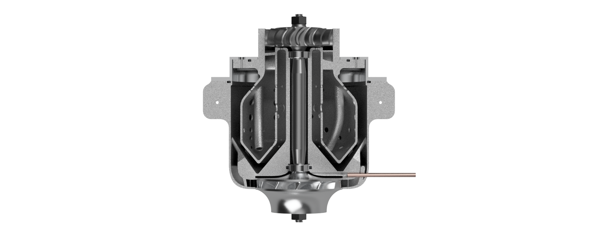
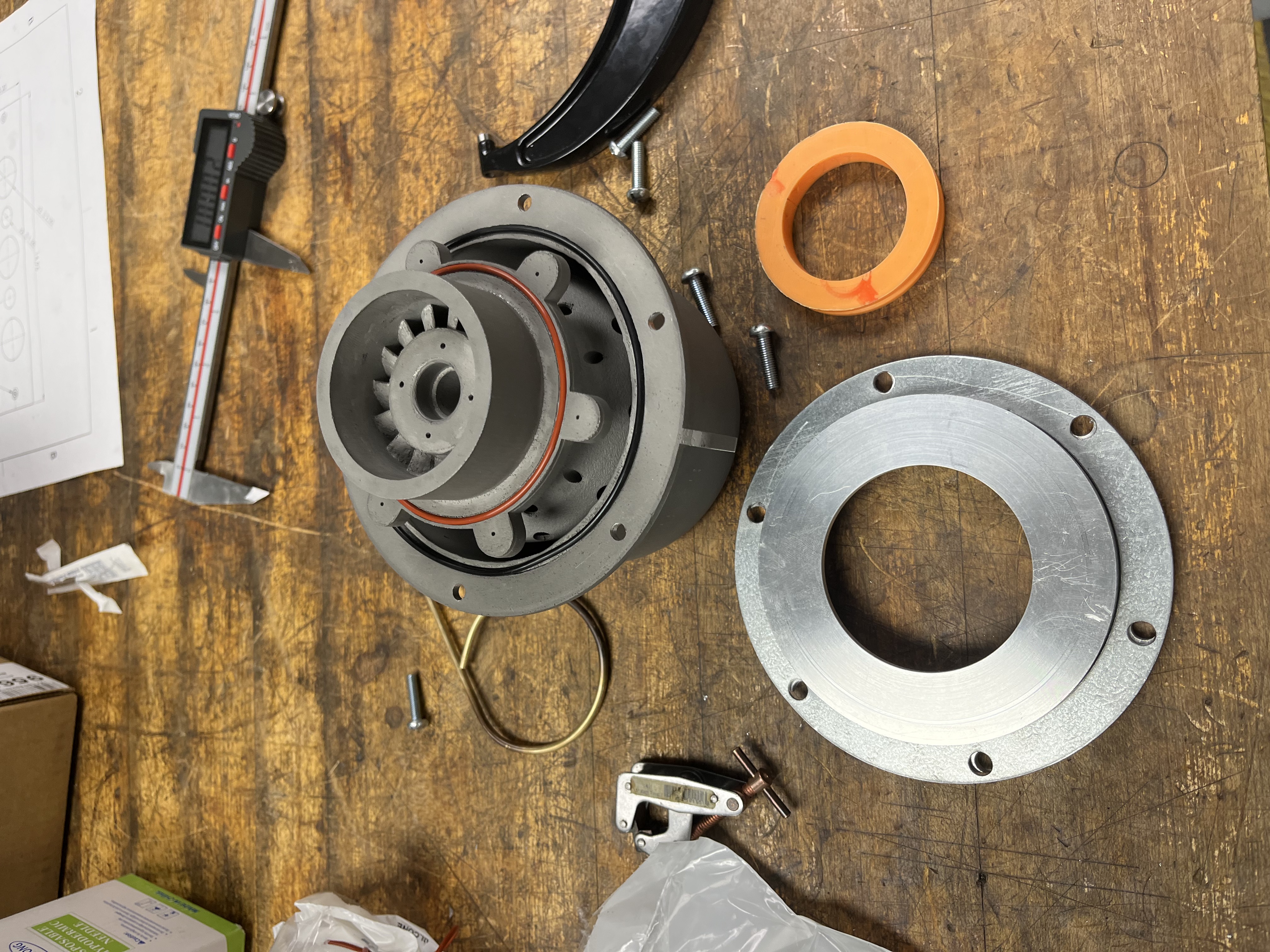
I contributed most of the final CAD for the engine, using Marco's research and first draft as reference. Our design involved considerably fewer parts than similarly sized engines thanks to the metal printing, allowing for one singular "body" part to contain our diffuser, guide vanes, combustion chamber, oil lines, and more. The engine was intended as a test for distributed manufacturing: designed for production without a factory or significant industrial investment in one place. In theory, one could produce our engine in a shipping container using only a printer, lathe, 3-axis mill, and hand tools.
The engine was sized for small UAVs and other single-use aircraft, systems that many defense startups believe will be used heavily in the future. It was designed to spin at 110,000 RPM on kerosene. We chose to use a closed impeller to reduce assembly steps and part count. Because the impeller and turbine were printed, they required substantial post-processing. After being turned down to spin concentrically, we balanced them via repeated back-and-forth rocking inside an aluminum tube, then removing mass on the side that was settled downward.
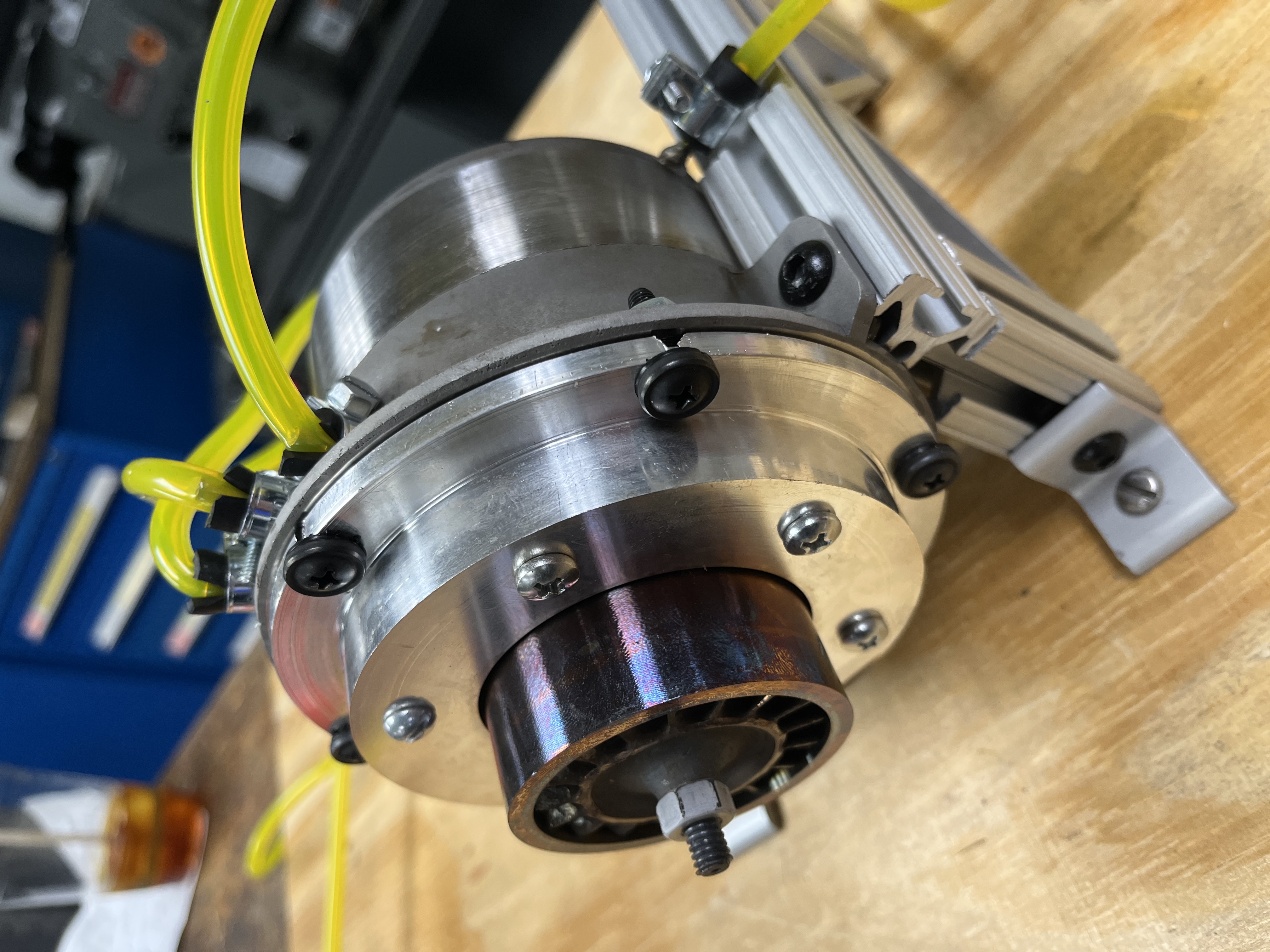
Post-machining the printed parts was the vast majority of the project. Unlike traditionally machined parts, nothing on our prints was true: every hole had to be drilled or reamed, faces turned, and rotating components balanced. Though time-consuming, we were able to get away without using any 5-axis milling or complicated tooling.
After post-processing everything (mainly turning down the faces that spun concentrically to each other), we were able to assemble our engine with press fits and a few bolts. The closed impeller allowed us to "simply" attach the turbine and impeller onto the shaft from opposite sides, nicely integrating into the body.
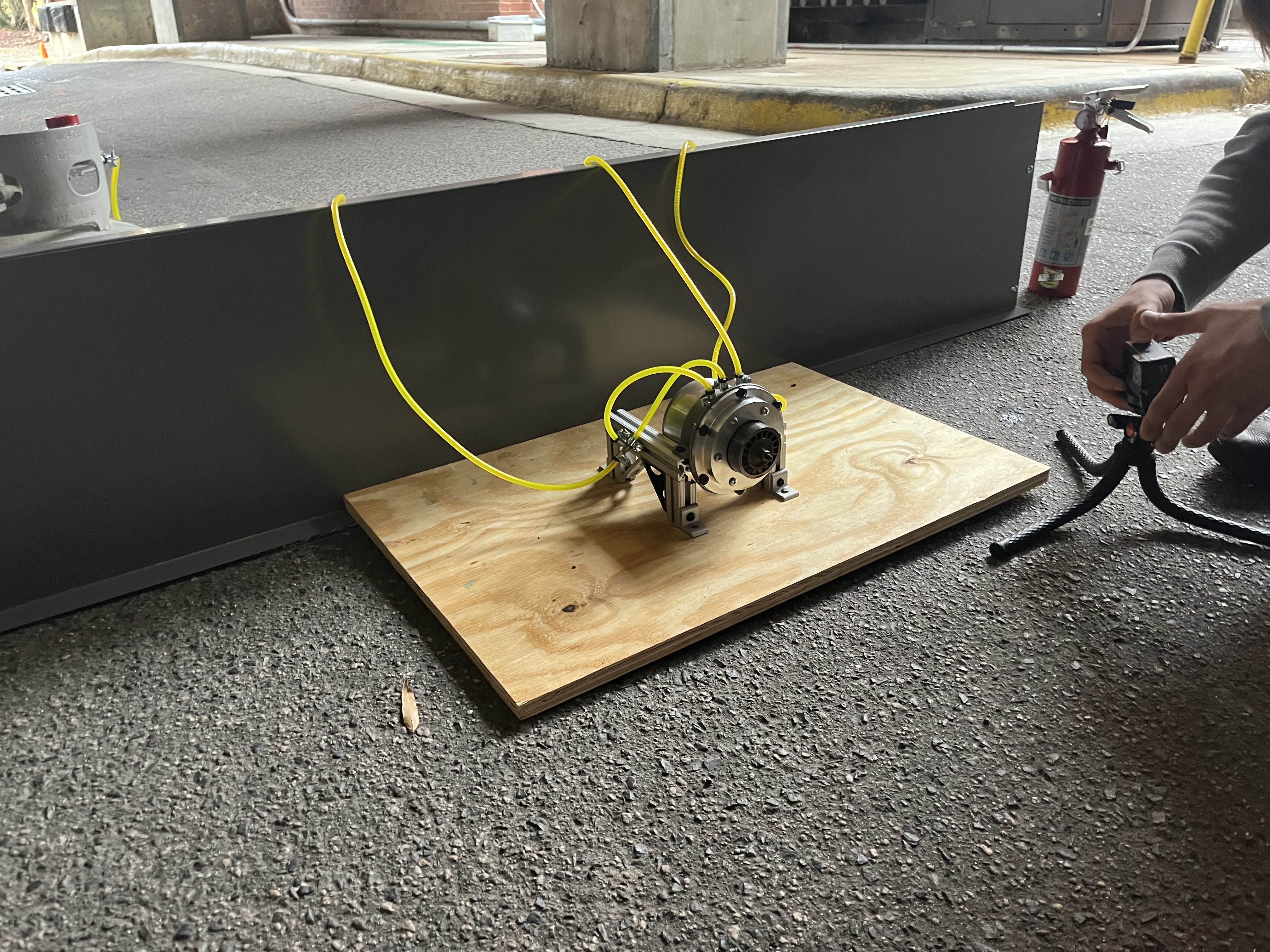
In our first test (pictured in the top right), we spun to an estimated 30,000 RPM on propane. We hypothesize that the difficulty our engine had in self-sustaining was due to pressure losses, most likely through the cautiously large clearance we machined between the compressor and the engine body. A broken hose for our pressure gauge exacerbated this problem.