Modular Differential 6DOF Arm
March 2026
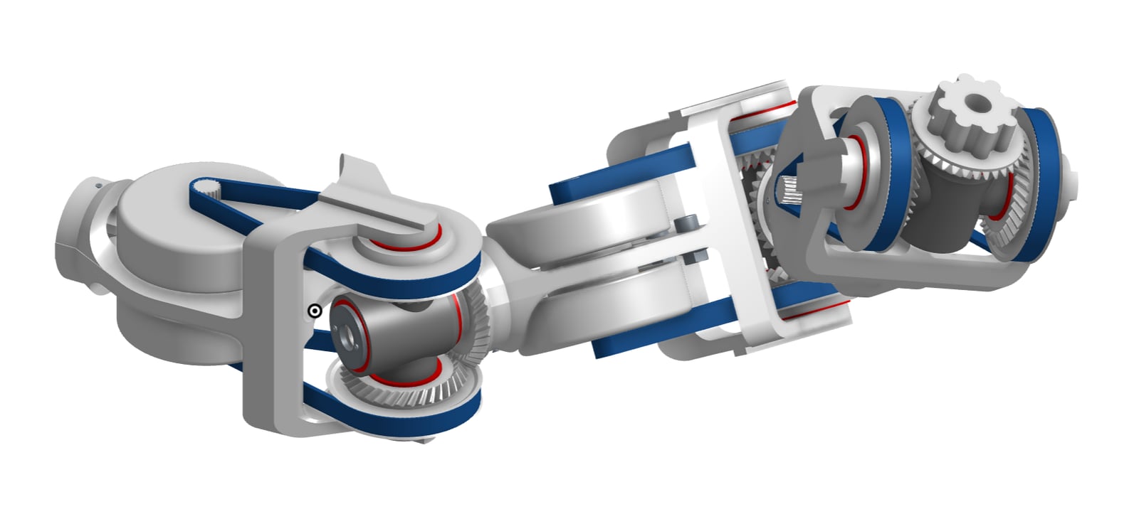
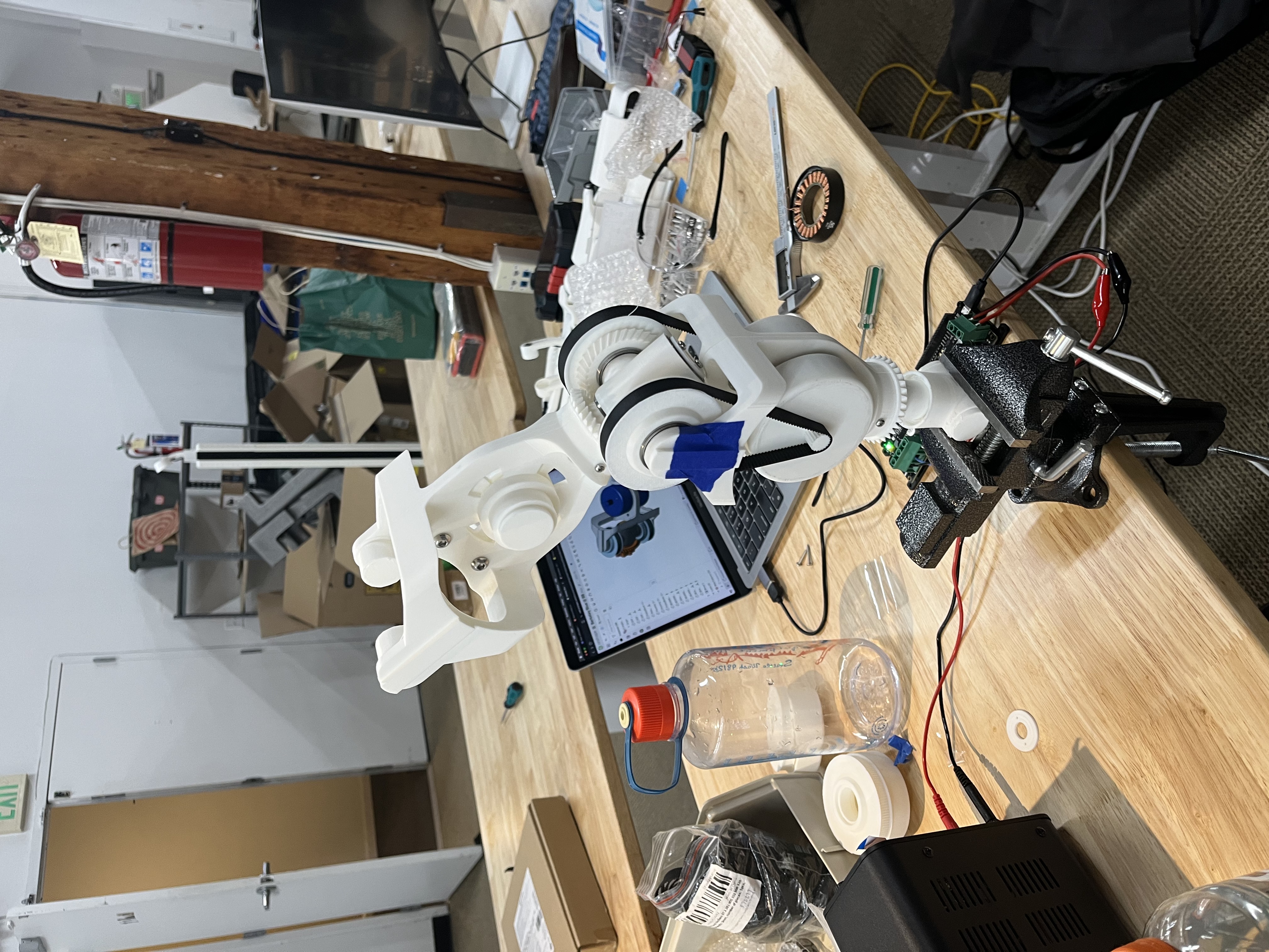
A 3D printed differential arm subassembly that stacks into further degrees of freedom, inspired by the Berkeley Blue.
tldr
- Role
- Solo design and build · during a 36-hour trip · March 2026
- Built
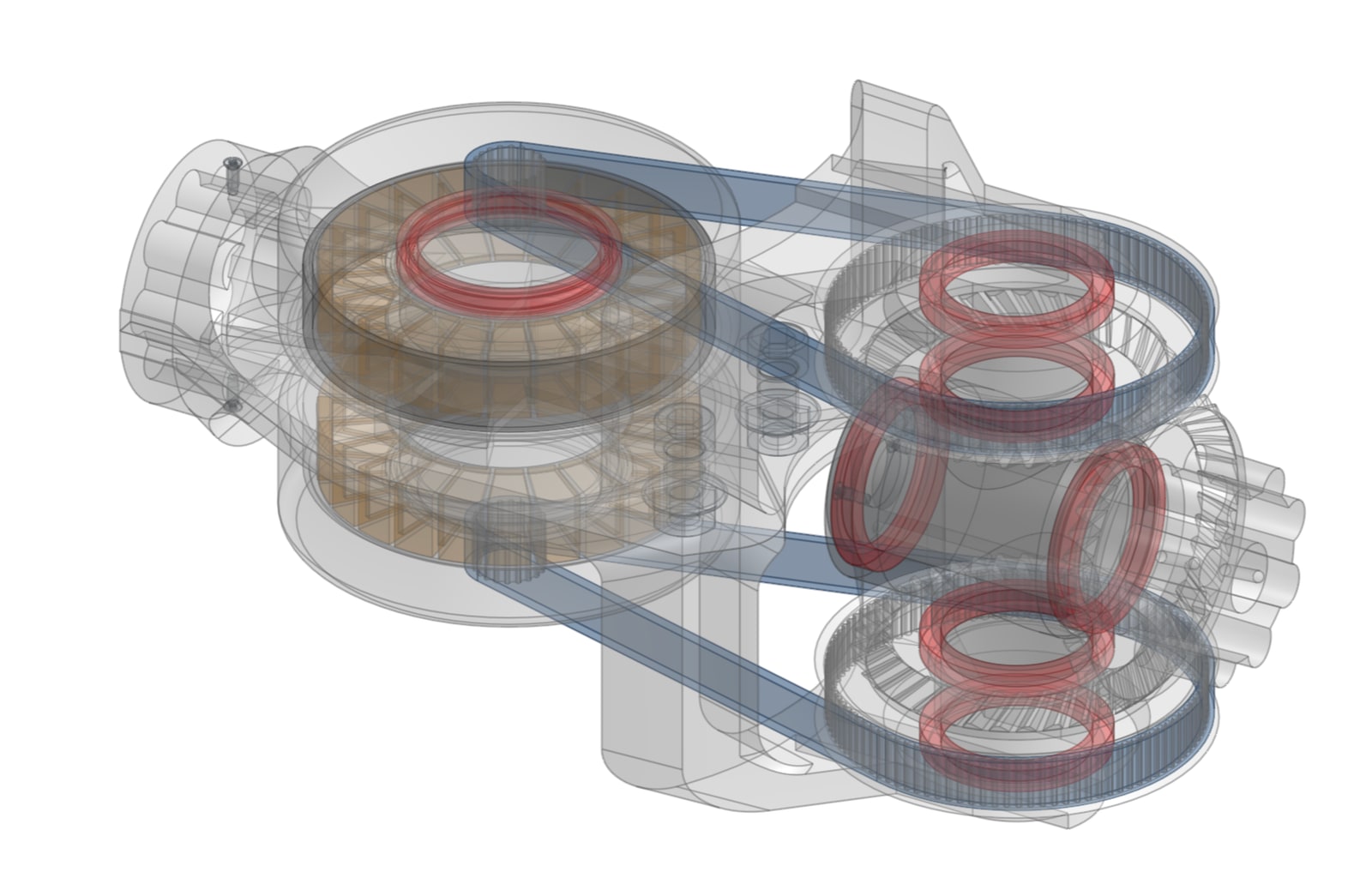
- Designed a stackable robot-arm joint where two frameless motors share a bevel-gear differential to drive two axes, with wiring routed through each joint
- Result
- Designed in under 12 hours; printed (~24 print-hours) and assembled a working module the next day
- Tools
- Onshape, bevel gear design, frameless motors, press-fit bearings, FDM 3D printing
There are a lot of 3D printed robot arms out there right now. So what's one more?
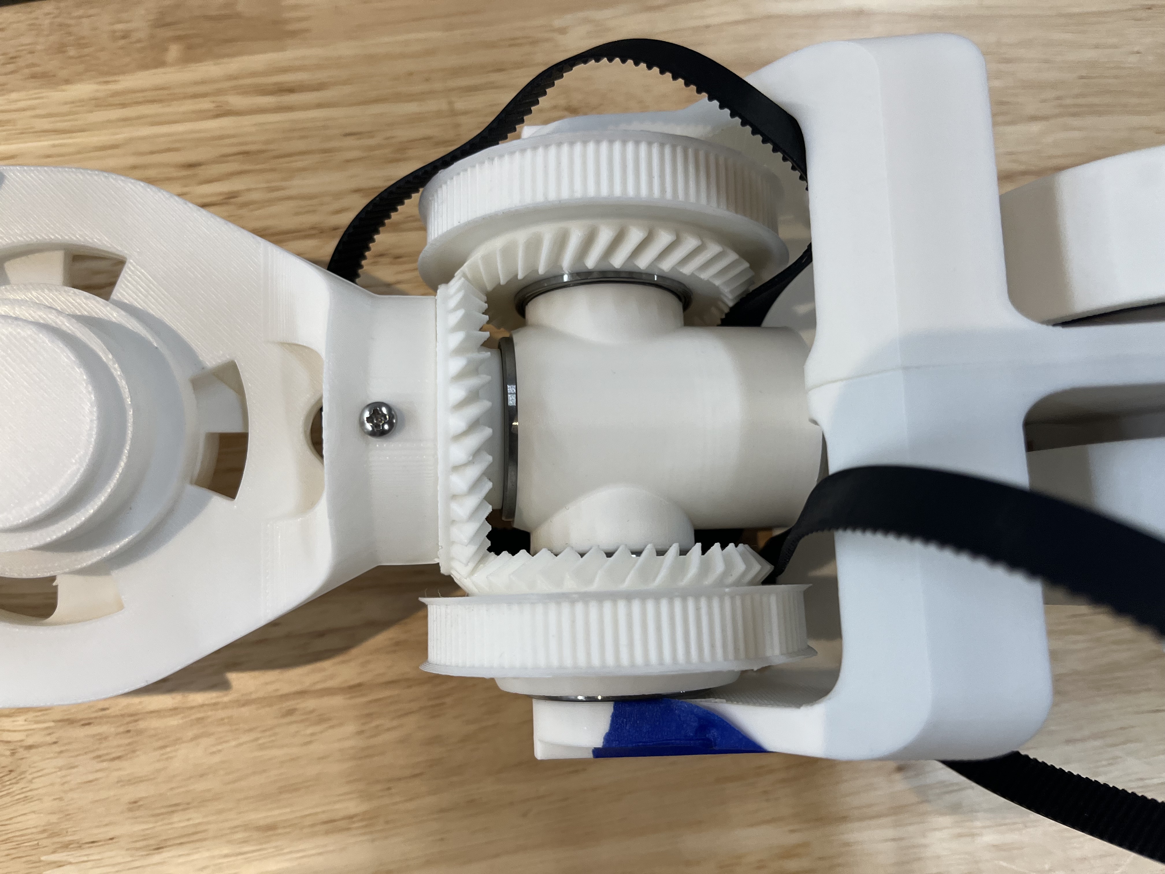
Jokes aside, I wanted to build an arm using differentials to make better use of the 6 motors traditionally used to individually achieve 6 degrees of freedom. With differential joints, one can approach a doubling in effective torque when performing limited movements. This is very interesting, since the high load tasks humans often perform generally have restricted degrees of freedom already (when you bicep curl, you don't find yourself rotating your forearm too). This had been done before by a team of researchers at Berkeley, though they still ended up at a $5,000 price point.
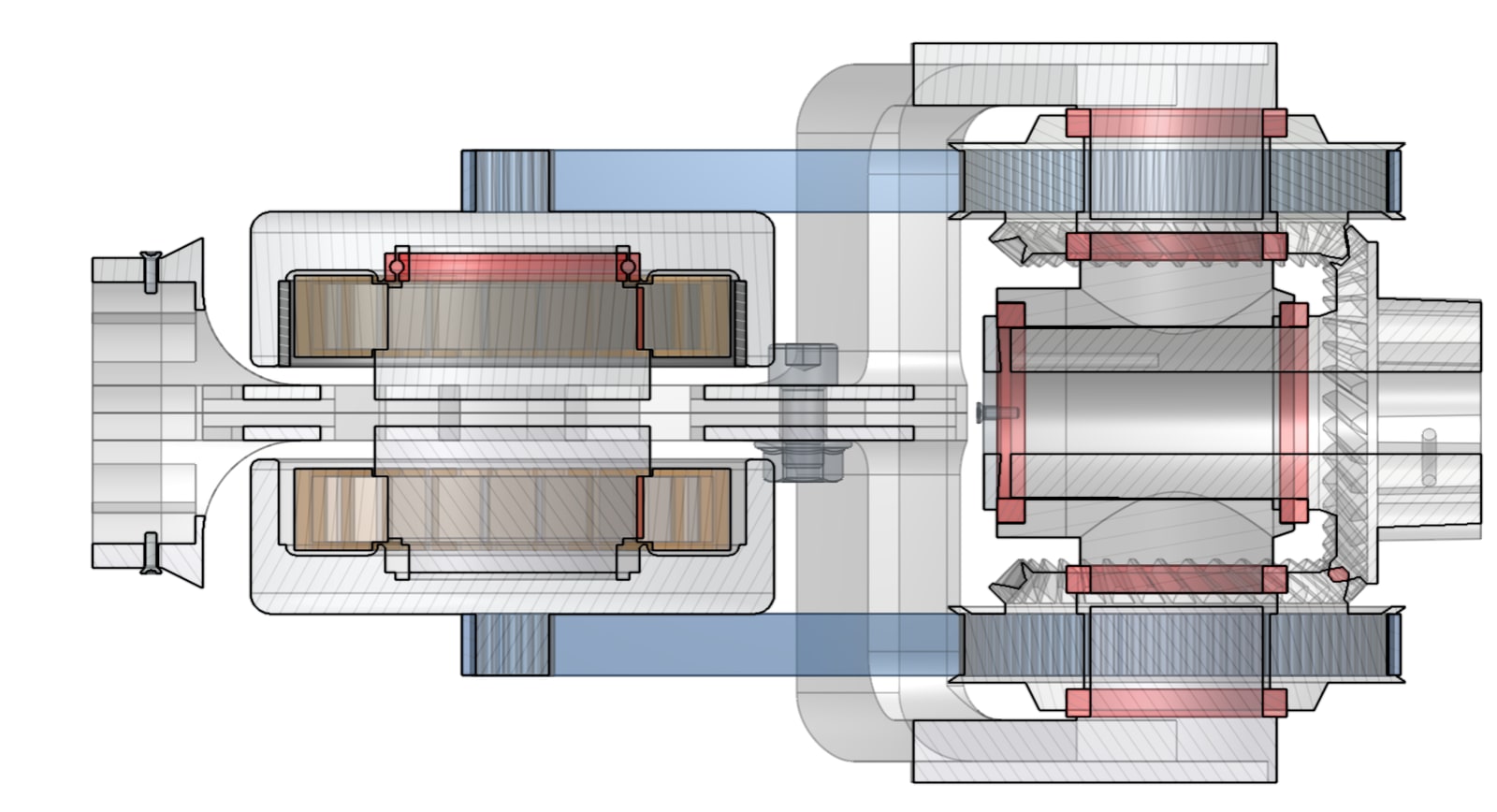
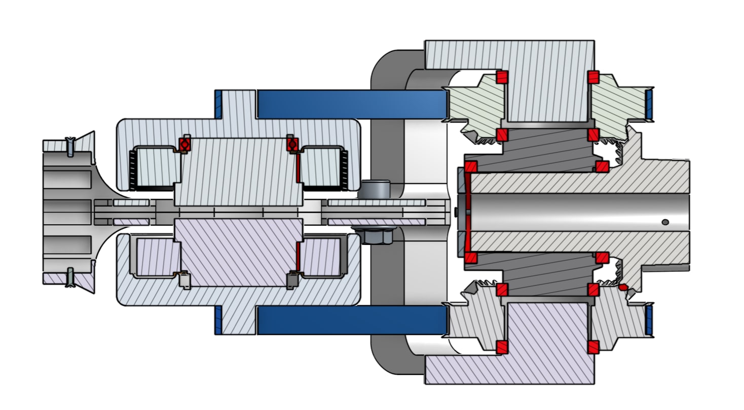
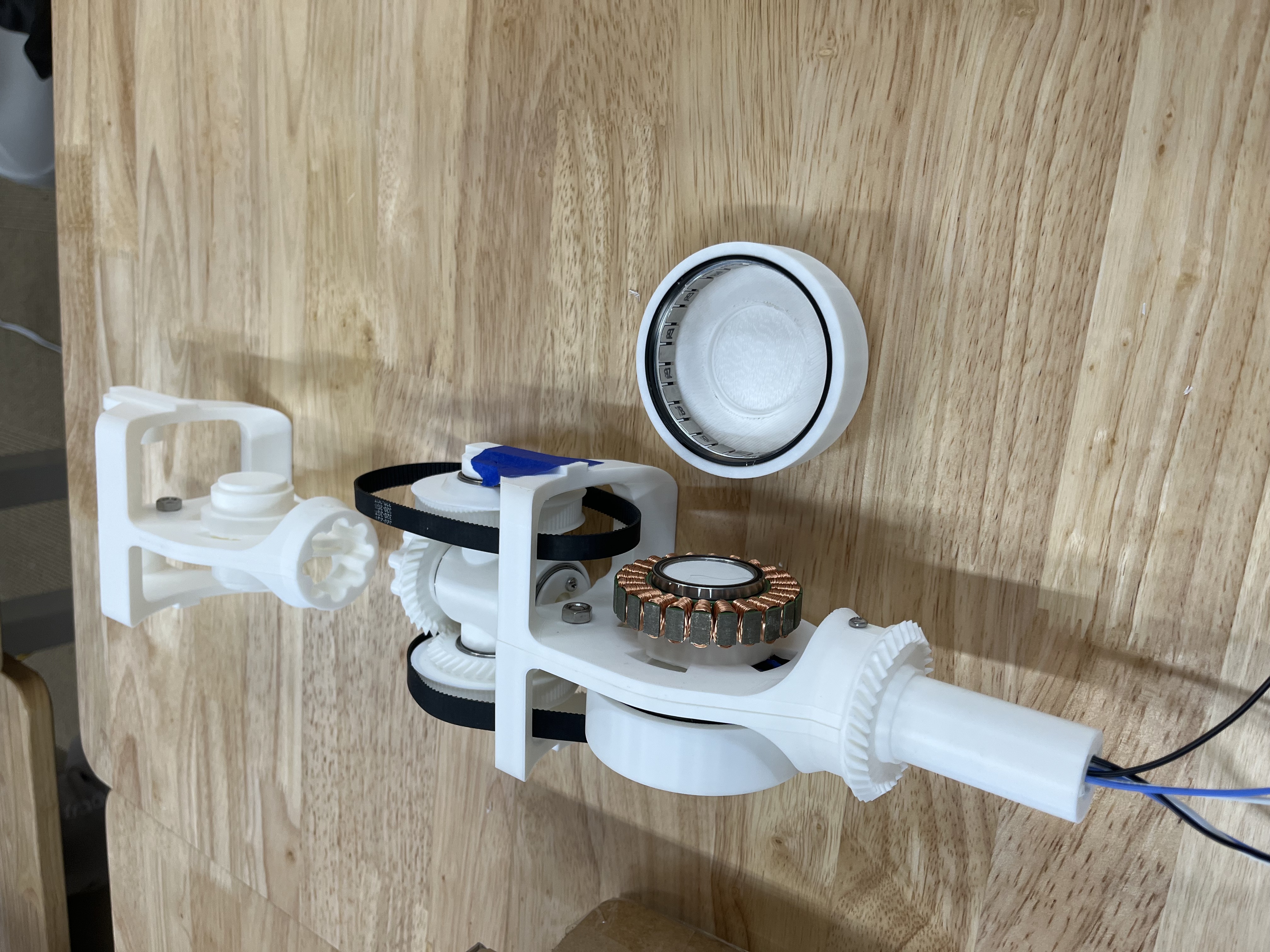
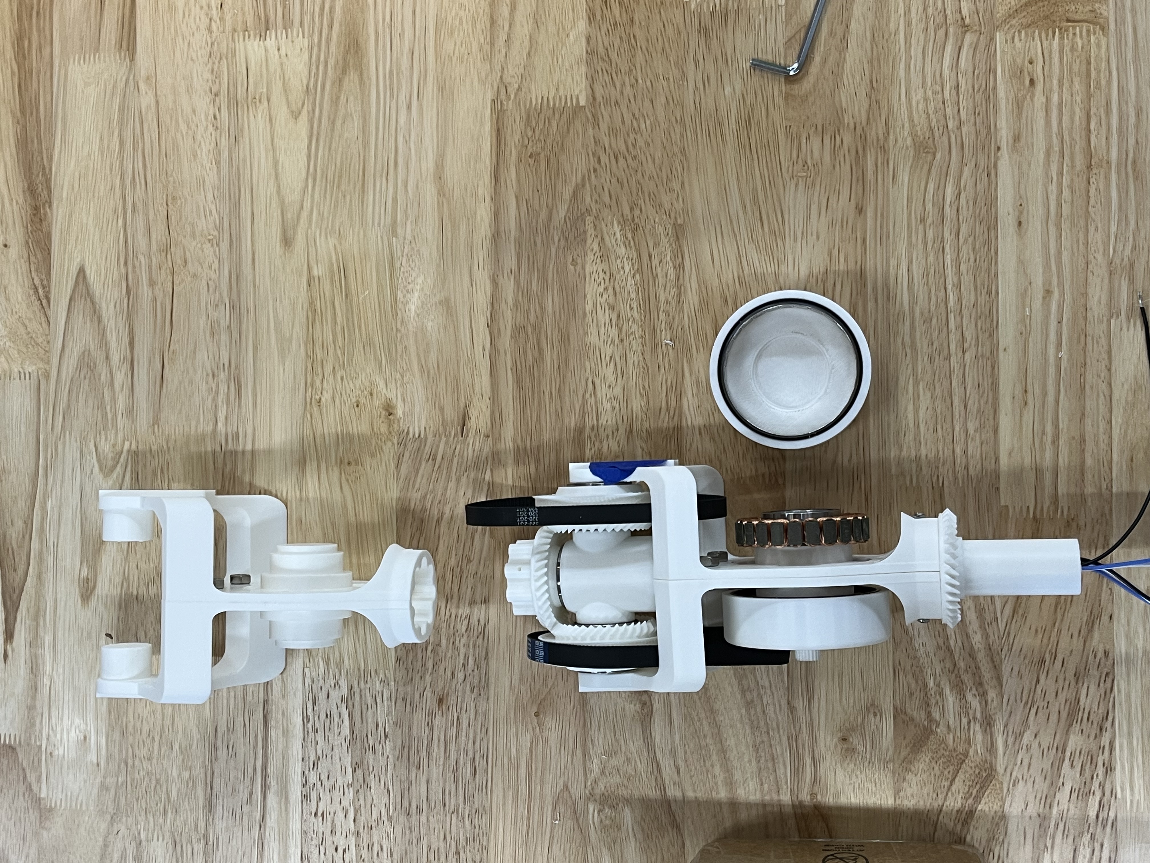
I designed my arm in just under 12 hours while hanging out with Brian Machado and assembled a module the next day (I was only in town for 36 hours). The arm is a series of 2DOF modules. Each module has two frameless motors, 8 press fit bearings, and two pulleys. Wiring passes through each module at the interface point where the ends connect into each other, allowing all controls to be handled somewhere past the shoulder.
Each module was printable with ~24 hours of printing time, which I parallelized across a few printers to make two overnight. I only had enough motor controllers to run one joint, but my single module worked as I'd hoped. I'd want to add sensors in future generations, and also importantly introduce printed housings like Berkeley's arm. My current design wasn't particularly rigid, so further printed housings would benefit precision and safety. The arm is moving very slowly in the attached video because the clone ODrive boards wouldn't update to be able to run open-loop, so they're running at very low RPM in a calibration state.
Design-wise, I modeled everything around one master sketch that captured all of the rotational symmetry of the arm module. I had to do some funny stuff to calculate the bevel gear teeth spacing properly, but the Onshape gear tooth plugin I installed meshed great after I accommodated for wall expansion. With low-cost frameless motors slowly becoming abundant on Chinese component websites, I wouldn't be that surprised to see a slightly more refined arm achieve large adoption as an open source platform. I would hold out to see some improvements in material creep resistance due to PLA's deformability before fully buying into printed robotics, but this project definitely gave me more optimism for the space to grow, and I'm beginning to see the appeal.